


The A3209Ex and A3210Ex integrated circuits are ultra-sensitive, pole
°°°°independent Hall-effect switches with a latched digital output. They are
°°°°especially suited for operation in battery-operated, hand-held equipment such as
°°°°cellular and cordless telephones, pagers, and palmtop computers. 2.5 volt to
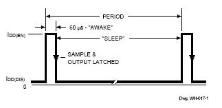
°°°°3.5 volt operation and a unique clocking scheme to reduce the average operat-
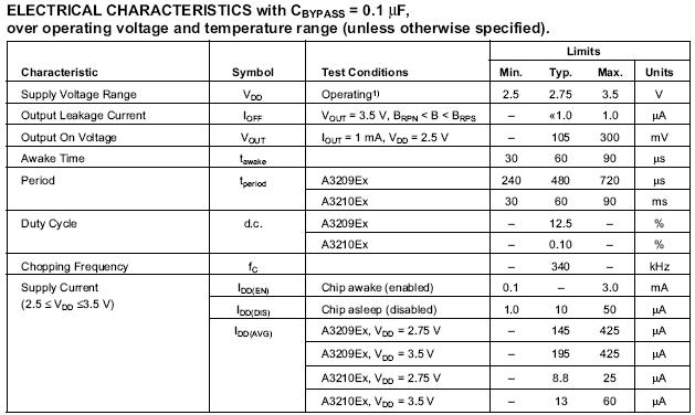
°°°°ing power requirements ®C the A3209Ex to 400 ?W, the A3210Ex to 25 ?W!
°°°°Except for operating duty cycle and average operating current, the A3209Ex
°°°°and A3210Ex are identical.
°°°°Unlike other Hall-effect switches, either a north or south pole of sufficient
°°°°strength will turn the output on; in the absence of a magnetic field, the output is
°°°°off. The polarity independence and minimal power requirement allows these
°°°°devices to easily replace reed switches for superior reliability and ease of
°°°°manufacturing, while eliminating the requirement for signal conditioning.
°°°°Improved stability is made possible through chopper stabilization (dynamic
°°°°offset cancellation), which reduces the residual offset voltage normally caused
°°°°by device overmolding, temperature dependencies, and thermal stress.
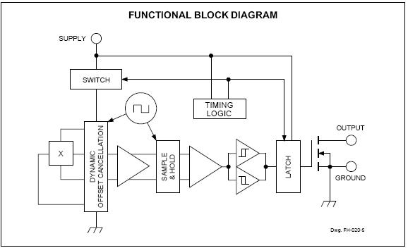
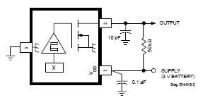
°°°°These devices include on a single silicon chip a Hall-voltage generator,
°°°°small-signal amplifier, chopper stabilization, a latch, and a MOSFET output.
°°°°Advanced BiCMOS processing is used to take advantage of low-voltage and
°°°°low-power requirements, component matching, very low input-offset errors,
°°°°and small component geometries.
°°°°The A3209Ex and A3210Ex are rated for operation over a temperature
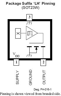
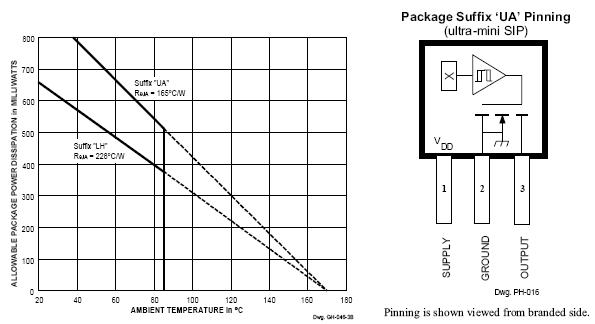
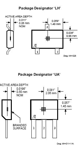
°°°°range of -40?C to +85?C. Two package styles provide a magnetically opti-
°°°°mized package for most applications. Suffix °ÆLH°Ø is a miniature low-profile
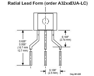
°°°°surface-mount package while suffix °ÆUA°Ø is a three-lead ultra-mini-SIP for
°°°°through-hole or surface mounting.
°°°°FEATURES
°°°°°ˆ Micropower Operation
°°°°°ˆ Operate With North or South Pole
°°°°°ˆ 2.5 V to 3.5 V Battery Operation
°°°°°ˆ Chopper Stabilized
°°°°Superior Temperature Stability
°°°°Extremely Low Switch-Point Drift
°°°°Insensitive to Physical Stress
°°°°°ˆ ESD Protected to 5 kV
°°°°°ˆ Solid-State Reliability
°°°°°ˆ Small Size
°°°°°ˆ Easily Manufacturable With Magnet Pole Independence
°°°°Always order by complete part number: the prefix °ÆA°Ø + the basic four-digit
°°°°part number + the suffix °ÆE°Ø to indicate operating temperature range + a
°°°°suffix to indicate package style, e.g.,
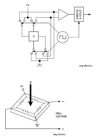
°°°°Chopper-Stabilized Technique. The Hall element can be
°°°°considered as a resistor array similar to a Wheatstone bridge. A
°°°°large portion of the offset is a result of the mismatching of these
°°°°resistors. These devices use a proprietary dynamic offset
°°°°cancellation technique, with an internal high-frequency clock to
°°°°reduce the residual offset voltage of the Hall element that is
°°°°normally caused by device overmolding, temperature dependen-
°°°°cies, and thermal stress. The chopper-stabilizing technique
°°°°cancels the mismatching of the resistor circuit by changing the
°°°°direction of the current flowing through the Hall plate using
°°°°CMOS switches and Hall voltage measurement taps, while
°°°°maintaing the Hall-voltage signal that is induced by the external
°°°°magnetic flux. The signal is then captured by a sample-and-
°°°°hold circuit and further processed using low-offset bipolar
°°°°circuitry. This technique produces devices that have an
°°°°extremely stable quiescent Hall output voltage, are immune to
°°°°thermal stress, and have precise recoverability after temperature
°°°°cycling. This technique will also slightly degrade the device
°°°°output repeatability. A relatively high sampling frequency is
°°°°used in order that faster signals can be processed.
°°°°More detailed descriptions of the circuit operation can be
°°°°found in: Technical Paper STP 97-10, Monolithic Magnetic
°°°°Hall Sensor Using Dynamic Quadrature Offset Cancellation
°°°°and Technical Paper STP 99-1, Chopper-Stabilized Amplifiers
°°°°With A Track-and-Hold Signal Demodulator.
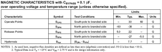
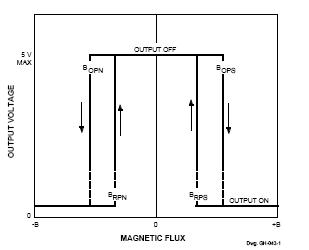
°°°°Operation. The output of this device switches low (turns on)
°°°°when a magnetic field perpendicular to the Hall sensor exceeds
°°°°the operate point BOPS (or is less than BOPN). After turn-on, the
°°°°output is capable of sinking up to 1 mA and the output voltage
°°°°is VOUT(ON). When the magnetic field is reduced below the
°°°°release point BRPS (or increased above BRPN), the device output
°°°°switches high (turns off). The difference in the magnetic
°°°°operate and release points is the hysteresis (Bhys) of the device.
°°°°This built-in hysteresis allows clean switching of the output
°°°°even in the presence of external mechanical vibration and
°°°°electrical noise.
°°°°As used here, negative flux densities are defined as less
°°°°than zero (algebraic convention) and -50 G is less than +10 G


Contact Person: liao
Skype: Aunytor
Email: 2885745253@qq.com