


PDF and WORD Download
A3046
A3046
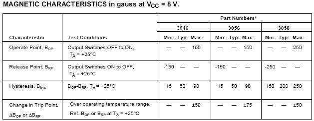
The A3046EU/LU, A3056EU/LU, and A3058EU/LU Hall effect
gear-tooth sensors are monolithic integrated circuits that switch in
response to differential magnetic fields created by ferrous targets。
These devices are ideal for use in gear-tooth-based speed, position,
and timing applications and operate down to zero rpm over a wide
range of air gaps and temperatures。 When combined with a back-
biasing magnet and proper assembly techniques, devices can be
configured to give 50% duty cycle or to switch on either leading,
trailing, or both edges of a passing gear tooth or slot。
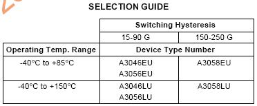
The six devices differ only in their magnetic switching values and
operating temperature ranges。 The low hysteresis of the A3046/56EU
and A3046/56LU makes them perfectly suited for ABS (anti-lock brake
system) or speed sensing applications where maintaining large air
gaps is important。 The A3046EU/LU features improved switch point
stability with temperature over the A3056EU/LU。 The high hysteresis
of the A3058EU and A3058LU, with their excellent temperature
stability, makes them especially suited to ignition timing applications
where switch-point accuracy (and latching requirements) is extremely
important。
All devices, when used with a back-biasing magnet, can be configured to turn ON
or OFF with the leading or trailing edge of a gear tooth or slot。 Changes in fields on the
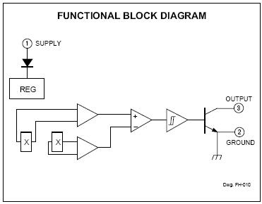
FUNCTIONAL BLOCK DIAGRAM
magnet face caused by a moving ferrous
mass are sensed by two integrated Hall
transducers and are differentially amplified by
on-chip electronics。 The on-chip temperature
compensation and Schmitt trigger circuitry
minimizes shifts in effective working air gaps
and switch points over temperature making
these devices ideal for use in ignition timing,
anti-lock braking systems, and speed mea-
surement systems in hostile automotive and
industrial environments。
Each Hall effect digital Integrated circuit
includes two quadratic Hall effect sensing
elements, a voltage regulator, temperature
compensating circuitry, low-level amplifier,
Schmitt trigger, and an open-collector output
driver。 The on-board regulator permits
operation with supply voltages of 4。5 to 24
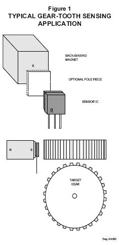
APPLICATIONS INFORMATION
A gear-tooth sensing system consists of the sensor IC, a back-
biasing magnet, an optional pole piece, and a target (Figure 1)。 The
system requirements are usually specified in terms of the effective
working air gap between the package and the target (gear teeth), the
number of switching events per rotation of the target, temperature and
speed ranges, minimum pulse duration or duty cycle, and switch point
accuracy。 Careful choice of the sensor IC, magnet material and
shape, target material and shape, and assembly techniques enables
large working air gaps and high switch-point accuracy over the system
operating temperature range。
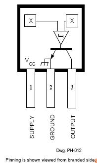
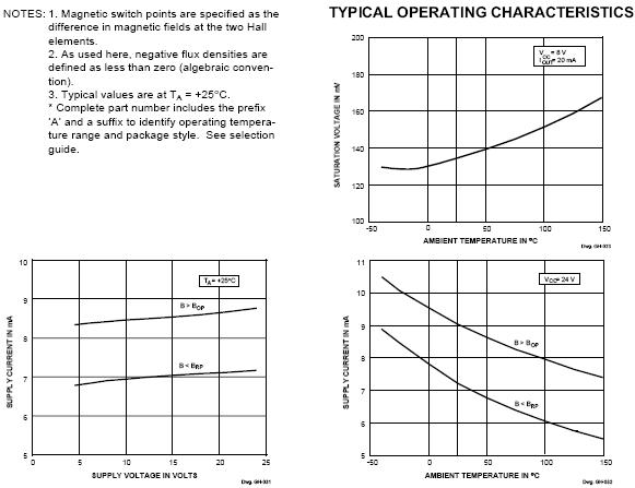
Naming Conventions。 With a south pole in front of the branded
surface of the sensor, a north pole behind the sensor, the field at the
sensor is defined as positive。 As used here, negative flux densities are
defined as less than zero (algebraic convention), e。g。, -100 G is less
than -50 G。
Magnet Biasing。 In order to sense moving non-magnetized
ferrous targets, these devices must be back-biased by mounting the
unbranded side on a small permanent magnet。 Either magnetic pole
(north or south) can be used
The devices can also be used without a back-biasing magnet。
In this configuration, the sensor can be used to detect a rotating ring
magnet such as those found in brushless dc motors or in speed
sensing applications。 Here, the sensor detects the magnetic field
gradient created by the magnetic poles。
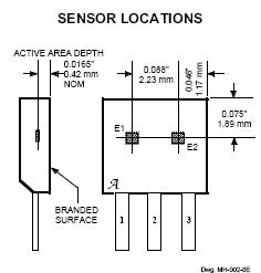
Sensor Operation。 The A3046EU/LU,
A3056EU/LU, and A3058EU/LU sensor ICs
each contain two integrated Hall transducers
(E1 and E2) that are used to sense a mag-
netic field differential across the face of the
IC (see SENSOR LOCATION drawing)。 Referring
to Figure 2, the trigger switches the output
ON (output LOW) when BE1 – BE2 > BOP and
switches the output OFF (output HIGH) when
BE1 – BE2 < BRP。 The difference between BOP
and BRP is the hysteresis of the device。
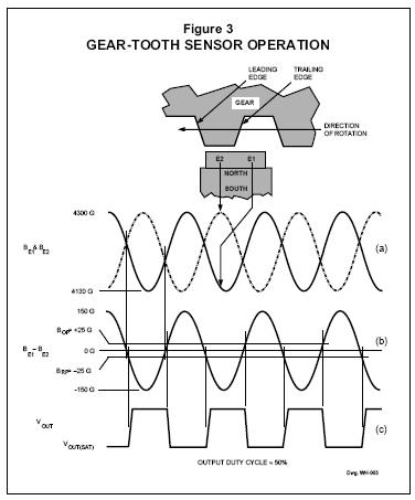
Figure 3 relates the output state of a
back-biased sensor IC, with switching
characteristics shown in Figure 2, to the
target gear profile and position。 Assume a
north pole back-bias configuration (equivalent
to south pole at the face of the device)。 The
motion of the gear produces a phase-shifted
field at E1 and E2 (Figure 3 (a)); internal
conditioning circuitry subtracts the field at the
two elements (Figure 3 (b)); and the Schmitt
trigger at the output of the conditioning
circuitry switches at the pre-determined
thresholds (BOP and BRP)。 As shown (Figure
3 (c)), the IC output is LOW whenever sensor
E1 sees a (ferrous) gear tooth and sensor E2
faces air。 The output is HIGH when sensor
E1 sees air and sensor E2 sees the ferrous
target。
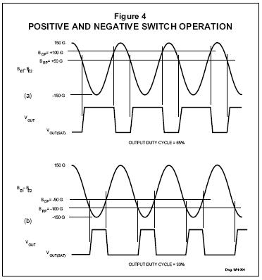
A gear-tooth sensor can be configured
(see ASSEMBLY TECHNIQUES) to operate as a
latch, a (positive) switch, or a negative
switch。 Note the change in duty cycle in
each of the cases (Figure 4)
In the configuration shown in Figure 3, such a device will switch ON
and then switch OFF on the leading or rising edge of the target tooth
(Figure 4 (a))。
A negative switch is a device where both the operate and release
points are less than zero gauss (negative values)。 In the configuration
shown in Figure 3, such a device will switch OFF and then switch ON
on the trailing or falling edge of the target tooth (Figure 4 (b))。
Speed sensors can use any of the three sensor configurations
described。 Timing sensors, however, must use a latch to guarantee
dual-edge detection。 Latches are most easily made using the
A3058EU or A3058LU device types
A latch is a device where the operate
point is greater than zero gauss and the
release point is less than zero gauss。 With
the configuration shown in Figure 3, such a
device will switch ON on the leading edge
and OFF on the trailing edge of the target
tooth。
A (positive) switch is a device where
both the operate and release points are
greater than zero gauss (positive values)。
SYSTEM ISSUES
Optimal performance of a gear-tooth
sensing system strongly depends on four
factors: the IC magnetic parameters, the
magnet, the pole piece configuration, and
the target。
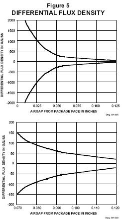
Sensor Specifications。 Shown in
Figure 5 are graphs of the differential field as
a function of air gap。 A 48-tooth, 2。5”
(63。5 mm) diameter, uniform wheel similar to
that used in ABS applications is used。 The
samarium cobalt magnet is 0。32” diameter by
0。20” long (8。13 x 5。08 mm)。 The maximum
functioning air gap with this typical gear/
magnet combination can be determined
using the graphs and the specifications for
the sensor IC。
In this case, if an A3056EU/LU sensor
with a BOP of +25 G and a BRP of -25 G is
used, the maximum allowable air gap would
be 0。110” (2。79 mm)。 If the switch points
change +75 G with temperature (BOP = + 100
G, BRP = +50 G), the maximum air gap will be
approximately 0。077” (1。96 mm)。
All system issues should be translated
back to such a profile to aid the prediction of
system performance。
Magnet Selection。 These devices can
be used with a wide variety of commercially
available permanent magnets。 The selection
of the magnet depends on the operational
and environmental requirements of the
sensing system。 For systems that require
high accuracy and large working airgaps or
an extended temperature range, the usual
magnet material of choice is rare earth
samarium cobalt (SmCo)。 This magnet
material has a high energy product and can
operate over an extended temperature range。
For systems that require low-cost solutions
for an extended temperature range, Alnico-8
can be used。 Due to its relatively low energy
product, smaller operational airgaps can be
expected。 At this time, neodymium iron
boron (NeFeB) is not a proven high-tempera-
ture performer; at temperatures above
+150?C it may irreversibly lose magnetic strength。 Of these three
magnet materials, Alnico-8 is the least expensive by volume and
SmCo is the most expensive。
Either cylindrical- or cube-shaped magnets can be used, as long
as the magnet pole face at least equals the facing surface(s) of the IC
package and the pole piece。 Choose the length of the magnet to
obtain a high length-to-width ratio, up to 0。75:1 for rare earths, or 1。5:1
for Alnico-8。 Any added magnet length may incrementally improve the
allowable maximum air gap。
Magnets, in general, have a non-uniform magnetic surface profile。
The flux across the face of a magnet can vary by as much as 5% of the
average field over a 0。10” (2。5 mm) region。 If a Hall sensor is placed
directly on a magnet face, the non-uniformity can appear to shift the
operating parameters of the sensor。 For example, if a device is placed
on a 3000 G magnet with ?2% face offsets, each of the operating
points might be shifted by ?60 G。 When offsets are present, the
operating characteristics may be greatly altered。
Pole Piece Design。 A pole piece may be used at the face of the
magnet to smooth out the magnet-face offsets。 A 0。020” (0。51 mm)
thick, soft-iron pole piece will bring the field non-uniformity down to
the ?1%-to-?3% range。 Note that pole pieces will minimize but not
eliminate the non-uniformity in the magnet face field。 Front pole pieces
will almost always result in a reduced maximum air gap。
Ferrous Targets。 The best ferrous targets are made of cold-rolled
low-carbon steel。 Sintered-metal targets are also usable, but care
must be taken to ensure uniform material composition and density。
The teeth or slots of the target should be cut with a slight angle
so as to minimize the abruptness of transition from metal to air as the
target passes by the sensor。 Sharp transitions will result in magnetic
overshoots that can result in false triggering
Gear teeth larger than 0。10” (2。54 mm) wide and at least 0。10”
(2。54 mm) deep provide reasonable working air gaps and adequate
change in magnetic field for reliable switching。 Generally, larger teeth
and slots allow a larger air gap。 A gear tooth width approximating the
spacing between sensors (0。088” or 2。24 mm) requires special care in
the system design and assembly techniques。
ASSEMBLY TECHNIQUES
Due to magnet face non-uniformities and device variations, it is
recommended that applications requiring precision switching utilize a
mechanical optimization procedure during assembly。 Without a pole
piece, the inherent magnet face offsets can be used to pre-bias the
magnetic circuit to obtain any desired operating mode。 This is
achieved by physically changing the relative position of the magnet
behind the sensor to achieve the desired system performance objec-
tive。 For example, with a rotating ABS gear, the objective might be a
50% duty cycle at maximum air gap。 Similar objectives can be set for
ignition (crank and cam position) sensing systems。
Non-precision speed sensing applications do not require optimiza-
tion。 For applications where mechanical optimization is not feasible,
non-zero speed devices such as the UGN/UGS3059KA ac-coupled
gear-tooth sensor are available。

Contact Person: liao
Skype: Aunytor
Email: 2885745253@qq.com