


DESCRIPTION
The X40430,X40431,X40434,X40435 combines
power-on reset control,watchdog timer,supply voltage
supervision,second and third voltage supervision,
manual reset, and Block Lock™ protect serial EEPROM
in one package.This combination lowers system cost,
reduces board space requirements,and increases
reliability.
Applying voltage to VCC activates the power-on reset
circuit which holds RESET/RESET active for a period of
time.This allows the power supply and system oscilla-
tor to stabilize before the processor can execute code.
Low VCC detection circuitry protects the user’s system
from low voltage conditions, resetting the system
when VCC falls below the minimum V TRIP1 point.
RESET/RESET is active until V CC returns to proper
operating level and stabilizes. A second and third volt-
age monitor circuit tracks the unregulated supply to
provide a power fail warning or monitors different
power supply voltage. Three common low voltage
combinations are available. However, Intersil’s unique
circuits allows the threshold for either voltage monitor
to be reprogrammed to meet specific system level
requirements or to fine-tune the threshold for applica-
tions requiring higher precision.
A manual reset input provides debounce circuitry for
minimum reset component count
The Watchdog Timer provides an independent protec-
tion mechanism for microcontrollers. When the micro-
controller fails to restart a timer within a selectable
time out interval, the device activates the WDO signal.
The user selects the interval from three preset values.
Once selected, the interval does not change, even
after cycling the power.
The memory portion of the device is a CMOS Serial
EEPROM array with Intersil’s Block Lock protection.
The array is internally organized as x 8. The device
features a 2-wire interface and software protocol
allowing operation on an I2C bus.
The device utilizes Intersil’s proprietary Direct Write™
cell, providing a minimum endurance of 100,000
cycles and a minimum data retention of 100 years.
FEATURES
Monitoring voltages: 5V to 9V
Independent core voltage monitor
Triple voltage detection and reset assertion
-Standard reset threshold settings. See selec-
tion table on page 2.
-Adjust low voltage reset threshold voltages
using special programming sequence
-Reset signal valid to V CC = 1V
-Monitor three separate voltages
Fault detection register
Selectable power-on reset timeout
(0.05s,0.2s,0.4s,0.8s)
Selectable watchdog timer interval
(25ms,200ms,1.4s or off)
Debounced manual reset input
Low power CMOS
-25µA typical standby current,watchdog on
-6µA typical standby current,watchdog off
Memory security
4Kbits of EEPROM
-16 byte page write mode
-5ms write cycle time (typical)
Built-in inadvertent write protection
-Power-up/power-down protection circuitry
-Block lock protect 0, or 1/2, of EEPROM
400kHz 2-wire interface
2.7V to 5.5V power supply operation
Available packages
-14 Ld SOIC, TSSOP
Pb-free plus anneal available (RoHS compliant)
APPLICATIONS
Communication equipment
-Routers, hubs, switches
-Disk arrays, network storage
Industrial systems
-Process control
-Intelligent instrumentation
Computer systems
-Computers
-Network servers
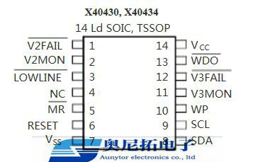
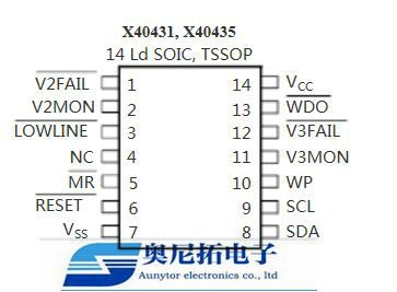
PIN CONFIGURATION
X40430, X40434
X40431, X40435
P/N Temp(0℃) Package
X40430S14-C 0℃ to 70℃
X40430S14I-C -40℃ to 85℃ SOIC14
X40430V14-C 0℃ to 70℃ TSSOP14
X40430V14I-C -40℃ to 85℃ TSSOP14
X40430S14-B 0℃ to 70℃ SOIC14
X40430S14Z-B 0℃ to 70℃ SOIC14
X40430S14I-B -40℃ to 85℃ SOIC14
X40430S14IZ-B -40℃ to 85℃ SOIC14
X40430V14-B 0℃ to 70℃ TSSOP14
X40430V14Z-B 0℃ to 70℃ TSSOP14
X40430V14I-B -40℃ to 85℃ TSSOP14
X40430V14IZ-B -40℃ to 85℃ TSSOP14
X40434S14-C 0℃ to 70℃ SOIC14
X40434S14I-C -40℃ to 85℃ SOIC14
X40434V14-C 0℃ to 70℃ TSSOP14
X40434V14I-C -40℃ to 85℃ TSSOP14
FROM: Company Name: Aunytor Electronic (HK) Co.,Ltd
Contact Person: Charlotte
Skype: Aunytor
whatsapp:+86 13537622113
Email: carrot@aunytorchips.com